This section shows the practices employed to assess the point cloud received from the camera topic /camera/depth/points. Even though the inner machinations of the specific functions used are out of scope of this project, their influence will be highlighted here to show their importance.
For completion’s sake, a point cloud has been included below to give an impression of what the input of the pipeline looks like as received from the point cloud topic.
Source
from IPython.display import HTML

HTML("""
<script type="module" src="https://unpkg.com/@google/model-viewer/dist/model-viewer.min.js"></script>

<model-viewer
    src="https://matt-rbt.github.io/Lab-Cleanup-Robot-using-the-Mirte-Master-Platform/models/pointcloud-compressed.glb"
    camera-controls
    auto-rotate
    style="width: 640px; height: 640px; background: #1c1917;">
</model-viewer>
""")

# IMPORTANT:
# The model path is an absolute GitHub Pages URL on purpose.
# A relative path like "./models/floor_with_cubes.glb" works locally in VS Code,
# but fails on the deployed MyST site because the page is served from /coverageplanners/.
# Do not change this to a relative path unless you also test the deployed site.To do this, a sample point cloud has been saved from the gazebo simulation and will be the subject of the filtering pipeline using the Open3D python library:
steps:
Crop the point cloud to include only points below a given height.
Copy a downsampled version of the pointcloud to speed up future calculations.
Iteratively detect planes and remove corresponding points from both point clouds. From there, the downsampled point cloud will not be used anymore.
Detect clusters from the remaining points.
Create bounding boxes for these clusters.
Reject boxes that overlap with the costmap.
Any remaining bounding boxes are published as detected objects.
The entire pipeline with steps’ individual effects has been included below:
First, the original point cloud is made using the depth image from the camera, as shown in Figure 1
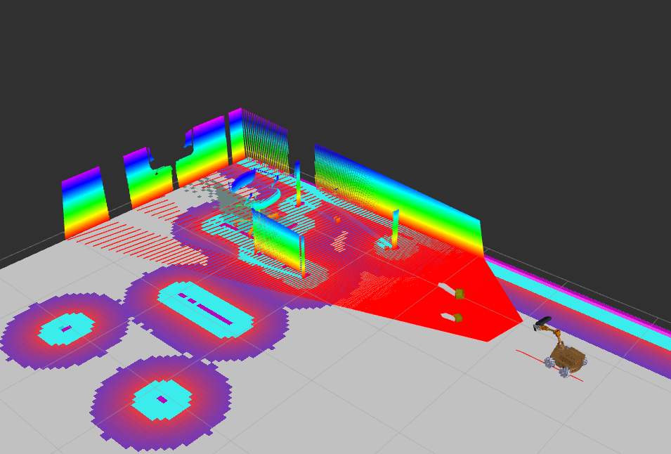
Figure 1:The point cloud as received from the camera topic including the eventual bounding boxes
Next, this point cloud is downsampled. Note that the resolution afterwards is still quite high. This is due to the fact that objects are very small, and if resolution is reduced dramatically, details of said objects will be lost, reducing bounding box accuracy. Below in Figure 2 is an example.
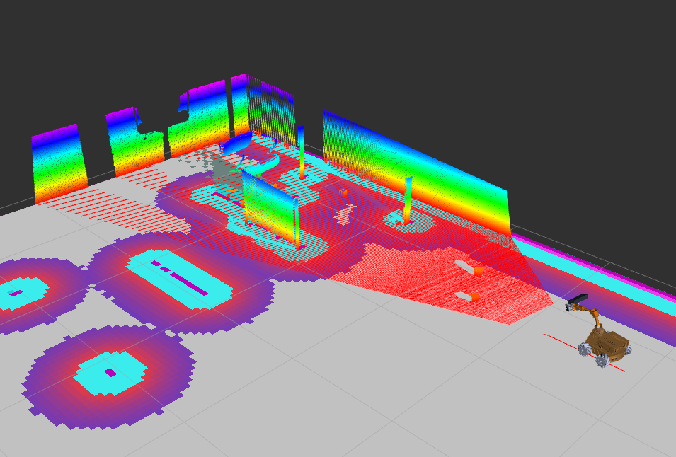
Figure 2:The downsampled point cloud
In the downsampled point cloud, planes will be detected using RANSAC plane segmentation Fischler & Bolles, 1981. With this, large planes such as walls and tabletops will be discarded from the point cloud, as can be seen in Figure 3.
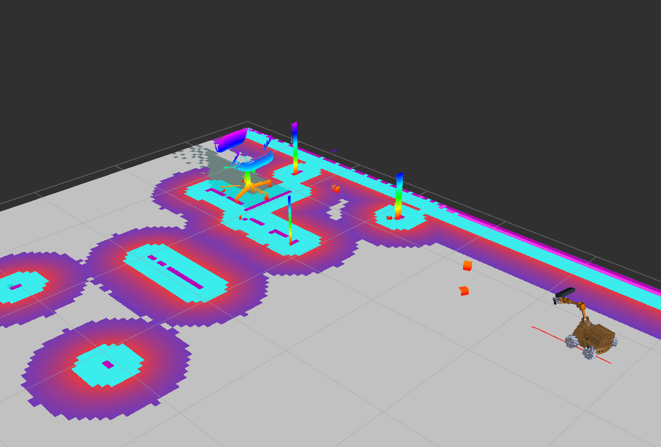
Figure 3:The plane-segmented point cloud
Now, the remaining points are cross referenced with the costmap obtained during mapping. Any points that is on the costmap is excluded from the point cloud, resulting in the point cloud as depicted in Figure 4
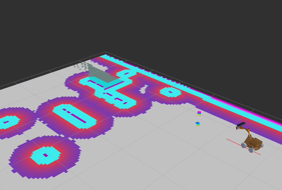
Figure 4:The point cloud containing only points belonging to free objects
Finally, the remaining points can be converted to clusters using Ester et al., 1996. This function enables the construction of bounding boxes for each cluster, which represents an object. Bounding boxes, however faint, can be made out in Figure 5 below.
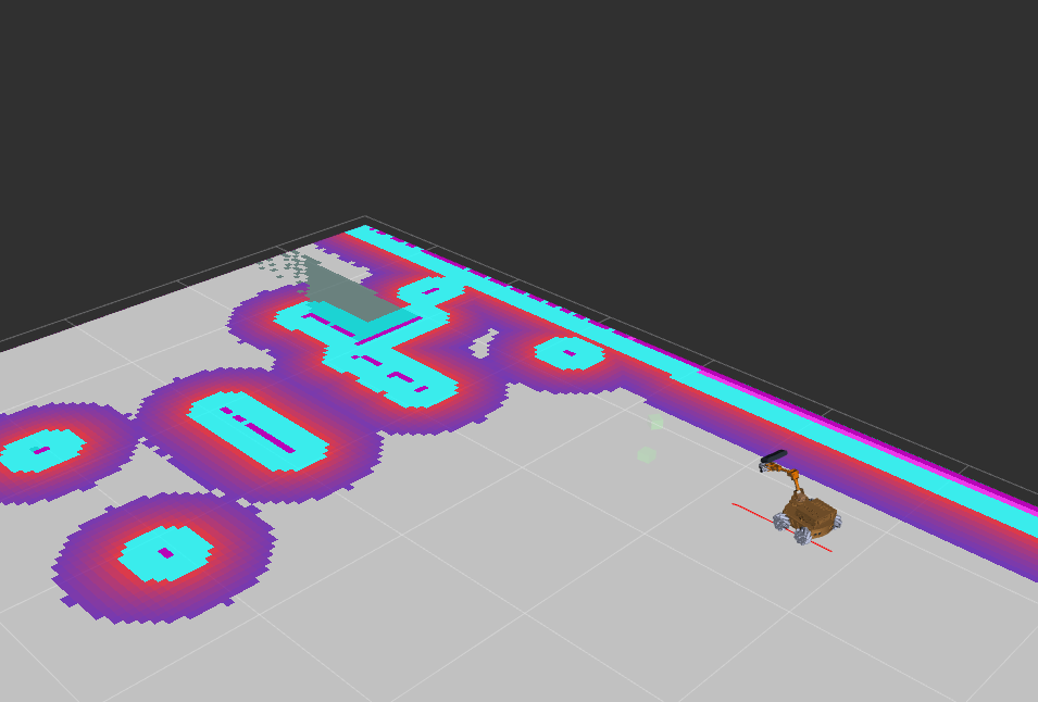
Figure 5:Bounding boxes (in front of the robot) are drawn around the remaining clusters.
Information about these bounding boxes is then published on a ros2 topic, to later be used to approach and pick up the corresponding objects.
- Fischler, M. A., & Bolles, R. C. (1981). Random sample consensus: a paradigm for model fitting with applications to image analysis and automated cartography. Commun. ACM, 24(6), 381–395. 10.1145/358669.358692
- Ester, M., Kriegel, H.-P., Sander, J., & Xu, X. (1996). A density-based algorithm for discovering clusters in large spatial databases with noise. Proceedings of the Second International Conference on Knowledge Discovery and Data Mining, 226–231.