This section describes the transition from simulation-based development to real-world testing on the MIRTE Master platform and the practical requirements involved in doing so.
To compare the implemented approaches, the study focused on practical performance indicators: whether the robot could complete a coverage run without losing track of its pose, whether objects could be detected and localized reliably, and whether manipulation could be executed accurately enough to place objects in the correct bin. These measures were used to evaluate the different planners and perception components.
The programs required for lab cleanup operation are brought up from two launch files; the first launches the navigation, perception and manipulation stacks, while the second runs the behavior tree. This setup allows different behavior trees to be tested without restarting the other subsystems. A brief description of each subsystem’s implementation is given below.
Coverage Navigation The coverage navigation system is implemented as an action server, meaning it plans and executes the coverage path in response to a request from an external client. The request specifies which coverage planner to use. As described in Coverage Planners, the coverage task is executed as a sequence of waypoint segments. During execution, the system continuously monitors the Nav2 action state and publishes progress feedback. If a stop or cancel request is issued, the current navigation task is interrupted and the run ends. If a pause request is issued instead, the active segment is interrupted, the remaining waypoints are stored, and the unfinished portion is re-queued so that the task can resume from the current location once the pause is lifted.
Manipulation
The manipulation system also consists of an action server, accepting goal requests from the behavior tree. It exposes a single action interface that handles named pose targets, Cartesian pose goals and gripper commands. For Cartesian goals, the server runs an IK solve against the wrist link, falls back to approximate IK if exact IK fails, applies time-optimal trajectory generation, and executes the resulting plan via MoveGroupInterface.
Perception
The perception pipeline consists of two independent nodes that run continuously alongside the behavior tree. The depth-based locator publishes detected object poses, which the behavior tree listens to via the blackboard. When the tree detects that objects are present, it pauses coverage navigation and approaches the closest detected object. Once the robot is within range, the 2D classifier is invoked via a service call to confirm the object’s class before the pick-and-place action is triggered. The classifier’s "target" or "waste" label is then passed directly to the manipulation system to determine which bin the object is placed in.
Figure 1 is a graphical overview of how the different systems interact
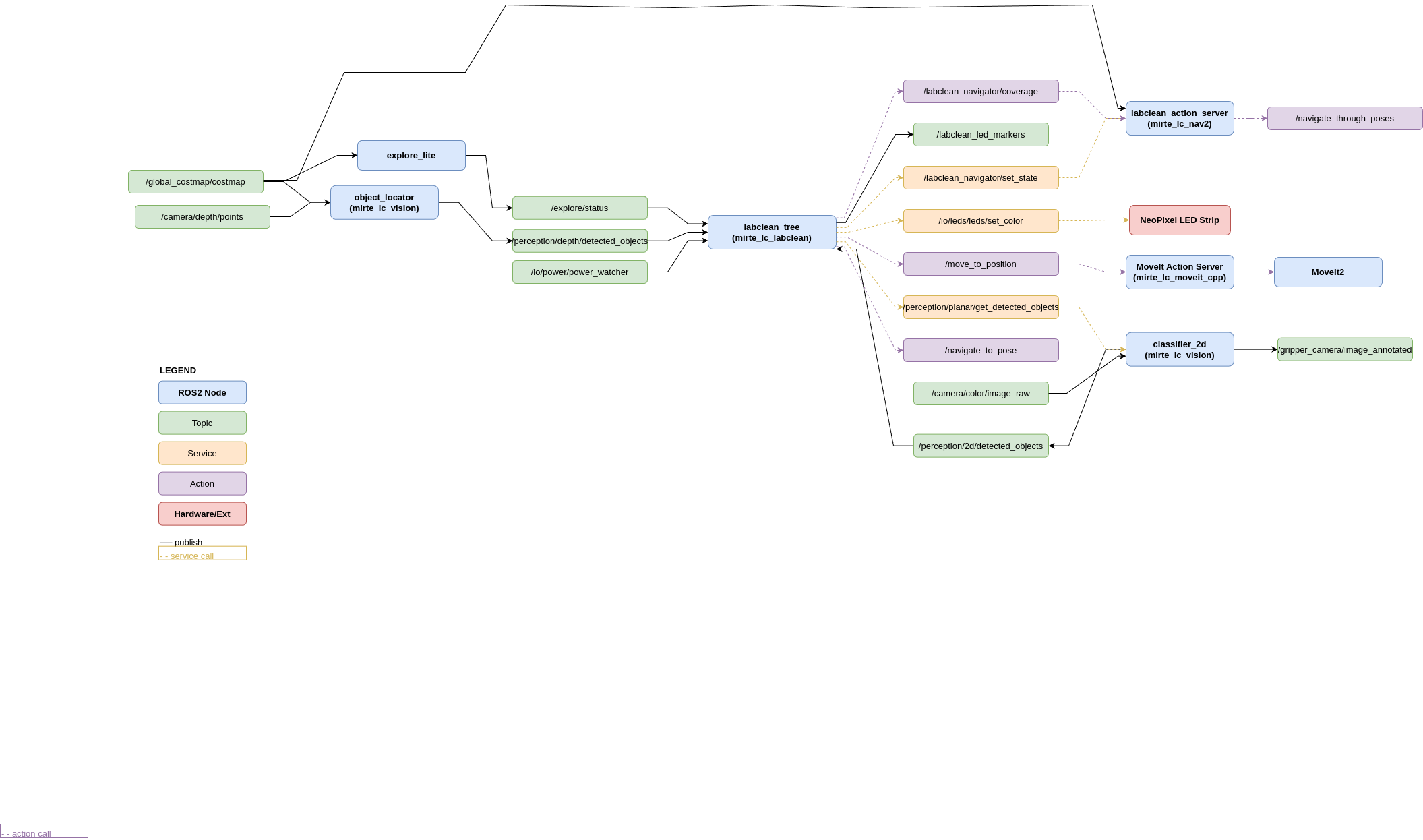
Figure 1:ROS 2 architecture.
Simulation
Development began without access to a physical robot. A Gazebo simulation environment was therefore set up to allow the software stack to be developed and tested in the interim. The simulated environment is shown below.
Source
from IPython.display import HTML

HTML("""
<script type="module" src="https://unpkg.com/@google/model-viewer/dist/model-viewer.min.js"></script>

<model-viewer
    src="https://matt-rbt.github.io/Lab-Cleanup-Robot-using-the-Mirte-Master-Platform/models/big_floor_with_cubes.glb"
    camera-controls
    auto-rotate
    exposure = 0.4
    style="width: 640px; height: 640px; background: #1c1917;">
</model-viewer>
""")Sim-to-Real pipeline
For the transition from simulation towards real-world testing, the codebase needed to be changed. The launch files were changed so that Gazebo was no longer used and use_sim_time parameters were set to false. To reduce the risk of collisions, the inflation radius and the robot radius in the Nav2 parameters were increased. Another change was the migration of processing tasks from the OrangePi 3B to a laptop connected to the MIRTE. Finally, all the sensors were tested and it was concluded that the depth camera was not positioned correctly, so its position was changed from the front of the robot to the gripper, allowing its viewing angle and distance to the object to be adjusted more effectively.
Testing Environment
For testing, an open, medium-sized room was chosen. The room needed to have sufficiently large open spaces for the robot to be able to plan its trajectories for the object-detection phase. Due to the use of mecanum wheels and camera-based object detection, the room also needed to have a mostly smooth, flat floor with a uniform colour.
Testing Objects
Due to the low video output quality of the included USB camera module, including significant motion blur and difficulties with exposure under different lighting conditions, the success rate of recognition and classification of electronic objects was too low. Additionally, most electronic waste had too low a profile to be recognized reliably by the depth camera. As a result, it was decided to 3D-print coloured shapes with a textured outer wall for grip. A custom dataset was created for the object-classification model to improve object-detection performance.